Last updated on Oct 27, 2010 |
|
|||||||||||||||||||||||||||||||||||||||||||||||||||||||||||||||||||||||||||||||||||||||||||||||||||||||||||||||||||||||||||||||||||||||||||||||||||||||||||||||||||||||||||||||||||||||||||||||||||||||||||||||||||||||||||||||||||||||||||||||||||||||||||||||||||||||||||||||||||||||||||||||||||||||||||||||||||||||||||||||||||||||||||
| Main page
Loudness Maximizers |
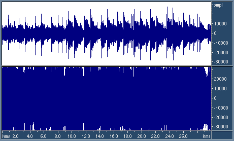
MaximizersThis article has been published in "Audio Producer" journal #1,2 2004. Maximizer (digital peak limiter) - is the dynamics processor that increases the level of audio signal during mastering. Sometimes other types of processors are also called maximizers: e.g. psychoacoustic processors like BBE Sonic Maximizer - we won't discuss them here. We'll review principles of work of dynamics processors and compare several popular software maximizers. Loudness and levelsThe loudness of audio depends not only on waveform levels (or sound pressure level), but also on spectral composition of the recording. However, once the spectral balance of the recording is defined and it's undesirable to change it, the way to increase loudness includes raising the signal level of the recording. Why do we need to increase loudness? There are 2 reasons. First of all, loud music often sounds better and more attractive than soft. That's why most producers strive for increase signal level during mastering: the commercial success of the recording may depend on signal levels. The second reason for loudness increase is in the desire to completely use the limited dynamic range of audio medium, such as CD or analog tape. It's also important to fully utilize the dynamic range of the playback device, so that the recording doesn't sink in noise. Most audio media typically constrains the peak level of the recorded signal by a certain full-scale level (above which clipping or distortion occurs), as opposed to RMS level (this is a simplified but realistic model for most digital and analog media). The ratio of the peak signal level to its RMS level is called crest factor (or peak factor). The rectangular wave has the crest factor of 0 dB. The crest factor of a sinusoid is 3 dB. Music recordings with a wide dynamics or sharp transients have high crest factors (20 dB and more), while strongly compressed recordings have a lower crest factor (10...15 dB). It's clear that when the peak level is constrained by the media, the recording with a lower crest factor can reach higher loudness. In order to decrease the crest factor of the recording, it's processed with dynamics processors (Fig. 1). Let's review their principles of operation.
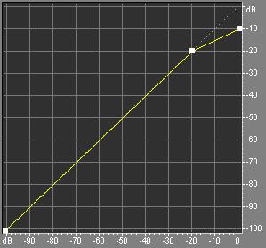
Dynamics processingDynamics processors are main devices used for manipulation with audio levels. The main principle of their operation is detection of input signal level and changing this level according to some rule. Main parameters of dynamics processors are the transfer function and attack/release time. Transfer function (not to be confused with a frequency response) is the dependence of the desired output level on the input signal level. According to the transfer function the device determines the gain to be applied to the input signal at each moment of time. The example of the transfer function is given at the Fig. 2. Such a dynamics processor is called compressor; this one passes all the sounds below -20 dB without change, and reduces level of all the sounds that are above -20 dB. So, the compressors makes loud sounds softer, compressing the dynamic range of the recording.
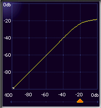
The bend in the transfer function is called knee. The input level corresponding to the knee is called threshold. The angle of the transfer function above the threshold determines the compression ratio. The ratio of 2:1 means that if the input level rises by 2 dB above the threshold, the output level should only rise by 1 dB. If the ratio is equal to 1, then the audio levels should not change. If the ratio tends to infinity, then the device should limit the output level by the value of the threshold. Such devices are called limiters, they limit the dynamic range. If the compression ratio is less than 1, e.g. 1:1.5, it means that the signal will be amplified as it goes above the threshold. Such devices are called expanders, they increase the dynamic range. There are other types of dynamics processors: gates, duckers, levelers and others - with their own transfer functions and parameters. Sometimes the transfer function is smoothed to prevent sharp edges (Fig. 3). This mode is called soft knee or soft threshold. The compressor with a soft knee starts reducing the signal level before it reaches the threshold.
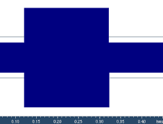
The operation of the dynamics processor can be described as follows: the device detects the input signal level and dynamically adjusts the output level, i.e. applies a certain time-varying gain envelope to the signal. For a good resulting sound, few requirements should be met. The most important of them is as follows: the gain envelope should be smooth, w/o breaks or sharp bends. Indeed, if the gain envelope has breaks, then the output signal will have breaks in the waveform, audible as clicks or crackle. Sharp bends in the gain envelope can also lead to signal distortion. For smoothing of gain envelope, dynamics processors have 2 parameters: attack time and release time. They define the reaction speed of the device to changes of the input level. The attack time means the reaction time to the input levels rising above the threshold (attack), and the release time means the reaction time to the input levels going below the threshold again. Fig. 4. Test signal before and after processing with a compressor. Let's assume that the input signal to the compressor consists of a section below the threshold following by the attack exceeding the threshold (Fig. 4). According to the transfer function, the compressor should pass the first section without change and attenuate the second section. The attack time means the time at which the compressor will change its gain level from 1 to the resulting gain prescribed by the transfer function. If the loud signal is followed by the softer section that is below the threshold, then the compressor enters the release state and increases its gain up to 1. The time it takes to increase the gain back to 1 is the release time. The definitions of attack and release times may differ by the manufacturer. Many devices consider the release time to be the time it takes the gain to go the half-way back, instead of a full way back. Often the gain returns to the target value following the exponent, and in this case only second definition of the release time makes sense. In some devices, the attack time is specified by the speed of gain change (dB/sec), or, on the contrary, by the time of gain change by 6 dB. Typically attack and release time and measured in milliseconds and can widely vary in different devices, depending on the particular application. For example, a typical attack time in compressors is 10...100 ms, and typical release time is 100...1000 ms. It's clear that the slower are attack and release, the slower will be changes in the gain envelope, and the smoother it will be. However, when the attack time is high, the compressor will miss reacting to short attacks above the threshold. This may be undesirable, e.g. for limiters. Another parameter often found in dynamics processors is the hold time (or release delay). This parameter sets the time that delays the release state of the processor after the input signal goes below the threshold. In other words, this parameter allows postponing the release by a certain time. Such a delay can help avoiding the situation when the processor is constantly switching between attack and release states, and improve the smoothness of the gain envelope. Now let's consider how dynamics processors detect the level of the input signal. This is typically done in one of 2 ways, and it's similar to level meters: peak and RMS. The first way is detection of instantaneous peak levels in the input signal. The second way is integration of the signal power over time, i.e. calculation of RMS. The peak detection is often used in limiters, when it is needed to limit peak levels of the signal by a certain threshold (e.g. before broadcasting the signal or recording it on the CD). The RMS detection is often used in compressors for leveling the loudness, because loudness is stronger related to RMS levels than to peak levels. Peak levels are always higher than RMS levels, and it should be considered during setup of the parameters. It's also clear that calculation of RMS levels requires a certain time interval for power integration, and the reaction time of the device cannot be much less than this integration time. In other words, the RMS compressor may miss short peaks of the signal and not reduce the gain timely. Another feature often encountered in dynamics processors is a side-chain - additional control input for audio signal. When this function is activated, there are 2 audio signals input to the device: through main and control inputs. The "control" signals is only used for level detection, and this detected level controls the level of the main audio signal according to the transfer function. Several interesting effects can be achieved using the side chain. If the signal input to the side chain is the same as the main signal, then the device will behave as usually without the side chain. If some another signal in input to the side chain, then the device will process the main signal using the amplitude profile of the control signals. For example, if the signal is passed through equalizer with inverse Fletcher-Manson (equal loudness) frequency response and then input to the side chain, then the amplitude of the control signal will more accurately correlate with the actual loudness of the main signal. So, the dynamics processor can be driven by the signals loudness as opposed to the signal level. This allows accurately leveling the perceived loudness of of the recording. Let's emphasize that the side-chain signal does not influence the timbre of the main processed signal. It only controls the gain envelope. When working with stereo recordings, dynamics processors are usually operating in linked channels mode, i.e. apply equal gain envelopes to left and right channels. Otherwise a stereo panning can be compromised.
To conclude this section, let's note that although compressors helped creating best worlds recording masters, inaccurate use of dynamics processing can irreversibly spoil a good recording. It's a mistake to to think that expander can undo the effects of compressor. If the dynamics is lost, there's nothing to expand. Moreover, both compressors and expanders have some inherent reaction times, making the exact restoration of dynamics hardly possible. MaximizersSo, our goal is to raise the level of the recording to maximal possible values without introducing significant distortion. The simplest way of achieving this is a well-known normalization, when the maximal peak level is found in the recording, and all the recording is amplified by this level, so that this peak reaches 0 dB. Any further amplification of the signal will lead to clipping (overload) of the signal and undesirable distortion. Obviously for any further increase in signal levels the dynamics processing can be used. If the recording is passed through a compressor or limiter, then peak levels are reduced, and additional amplification becomes possible without clipping. What should be used for raising levels: compressor or limiter? A known mastering engineer Bob Katz recommends using a compressor when the audible change is desired to its dynamics. A limiter should be used when any changes but the loudness are undesirable. Maximizer is the dynamics processor consisting of a peak limiter followed by the make-up gain. Often maximizers also have the word length reduction section, which we will not discuss here. Main controls of the maximizer are threshold level and attack/release settings. Some maximizers also have a "ceiling" control, allowing to reduce the output signal level below 0 dB and leave some headroom for a possible further processing. For example, if the maximized recording is supposed to be encoded to mp3, then the waveform shape can change, which may lead to clipping during decoding. Even if no further processing or encoding is planned, some headroom may be useful for adding a dithering noise during the following bit depth reduction. The lower is the threshold, the stronger is the limiting of the dynamic range, and the larger headroom is available for the subsequent amplification. So, lower threshold values lead to louder audio output.
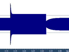
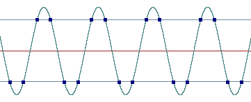
There's no issues with the make-up gain amplifier, so let's switch directly to the limiter. The goal of maximizer is to maximally increase the level of the signal and to avoid clipping, i.e. not to allow instantaneous waveform levels to exceed 0 dB. This means that only peak detection method is suitable for maximizers. A maximizer should trace signal peaks and construct the gain envelope so that instantaneous signal level does not exceed the threshold. When the input level is below the threshold, the signal should be passed unchanged. But when the input level exceeds the threshold, the limiter should attenuate the signal, so that it fits below the threshold. Since we want the gain envelope to be smooth, without breaks or sharp bends, the limiter needs to know the amplitudes of the waveform in some nearest future time moments. Indeed, without such knowledge any sharp over-threshold attack in the input signal would require the limiter to instantly reduce the gain to prevent exceeding the threshold. Such an instantaneous change in gain is the undesirable break or sharp bend in the gain envelope. So, for construction of a smooth gain envelope, the limiter needs to know the waveform levels in some future time. Since there's no way to reliably predict future waveform from the previous waveform, this look-ahead functionality is implemented by introduction of a small processing latency (delay of the output signal with respect to the input signal). In this way, when outputting the signal corresponding to time moment t, the limiter actually knows the input signal up to t+T, where T is the latency. This is similar to the news channel that is retranslating another news agency with a delay of 10 minutes. In every moment of time, employees of the news channel know the news in advance by 10 minutes, and can modify the programme for better quality of reporting. It should be remembered that the latency introduced by the limiter can be undesirable in certain situations. For example, adding a limiter to a mixer's channel insert will delay the sound of the channel with respect to other channels, which can lead to timbre changes during mixing of channels. Fortunately, maximizers are typically used on the whole mix during mastering, and in this case latency is not an issue. If some maximizer works in realtime and doesn't introduce any latency, it means that it either allows the signal to exceed threshold, or its gain envelope has breaks. The latency should also be considered when there's a need to synchronize channels in realtime audio processing programs. If the processing is not performed on realtime, then the host application can usually compensate for the delay, i.e. "align" the output signal of maximizer in time. Typically latency of maximizers is small, below 10 ms, with a few exceptions. Using the look-ahead values of peak levels, the limiter can build the smooth gain envelope and start attenuation before the attack actually arrives. In other words, the limiter should construct the gain envelope as a series of pits, where the depth of pits will depend on peak levels that exceed the threshold, and the width of pits will depend of attack and release times (Fig. 5). It's clear that wider pits mean that longer signal segments will be attenuated, and the overall loudness of the output signal will be lower. That's why the loudness of the output audio depends not only on the threshold level, but also on the attack/release time, and on the shape of the gain envelope during attack and release.
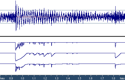
Controlling attack and release timeWhen the signal is multiplied by the gain envelope, some new harmonics can appear in its spectrum. Lower attack and release times lead to louder resulting audio, but also mean that the gain envelopes will change faster, and more intermodulation distortion will be generated. When the attack/release times are low, intermodulation distortion becomes especially noticeable during bass tones of high amplitude and with a period of equal or higher than the attack/release time. This can be demonstrated on test signals which are sums of sinusoids with different frequencies (the standard test of intermodulation distortion, Fig. 6).
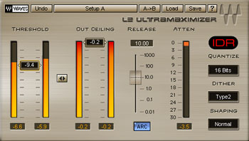
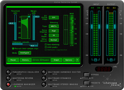
When attack/release times are large, the so called pumping artifact appears - drops of loudness around transients (Fig. 5). Around each transient the gain envelope has a shape of a wide pit, dropping the level of the surrounding audio. This is audible as trembling or drop-outs of loudness. So, the choice of attack/release time is a trade-off between intermodulation distortion and pumping artifact. Let's introduce the concept of aggressiveness of a maximizer. We'll say that a maximizer A is more aggressive than maximizer B if at the same setting of the threshold maximizer A produces louder output audio (judged by RMS levels). Clearly, aggressiveness depends on the attack/release time and on the shape of the gain envelope during attack/release states. In most maximizers, the user manually sets attack and release time after selecting the threshold level. If intermodulation distortion becomes audible, the aggressiveness is reduced by increasing attack/release time. If the distortion is inaudible, a higher aggressiveness can be attempted in order to achieve higher loudness and less pumping. Deeper limiting often requires longer attack/release times to avoid distortion. There is a way to automatically adjust the aggressiveness of the maximizer by the analysis of the input audio signal. Indeed, if the input signal has sharp transients, a higher aggressiveness is beneficial for reduction of pumping. Intermodulation distortion will not happen in this case, because infrequent short peaks will not cause periodic changes in the gain envelope, leading to intermodulation distortion. Moreover, the human ear has low sensitivity to short-term (less than 6 ms) distortions. In this way, the maximizer can quickly react to single transient peaks and quickly return to the unity gain. On the other hand, if the input signal contains frequent, periodic over-threshold spikes, then the aggressiveness of the maximizer should be reduced (by increasing the attack/release time), to avoid distortion. If such an adjustment of aggressiveness is performed adaptively, using the analysis of the input signal, then the average aggressiveness of the maximizer can be significantly increased without audible distortion. One of the first maximizers implementing this strategy is Waves L2 in ARC mode (Auto Release Control). It should be mentioned that the term "Auto Release Control" is slightly misleading, as it doesn't precisely describe the principle of operation of L2. This maximizer uses a little more complex way of construction of the gain envelope by combining 2 different gain envelopes: the aggressive one and the non-aggressive one. During infrequent transients, the aggressive envelope is used; during frequent, periodic spikes - a certain combination of 2 envelopes is used. This allows achieving louder and less distorted sound than by a simple adjustment of the release time. A similar algorithm is implemented in iZotope Ozone 3 maximizer.
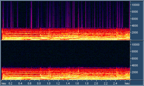
Inter-sample clippingMost loudness maximizers are digital processors. Indeed, it's almost impossible to implement the look-ahead feature in the analog world, so analog peak limiters are limited to either instant attack time (leading to breaks in the gain envelope) or failing to limit some transients and allowing clipping. On the other hand, digital maximizers having look-ahead can react on transients in advance, a few milliseconds before the peak arrives.
The goal of most digital maximizers is to prevent clipping of the digital waveform, i.e. to constrain all the digital samples below the threshold. However such a limiting does not guarantee that the analog waveform reconstructed from the digital signal will also be limited by the same threshold. Indeed, the analog waveform, while smoothly oscillating between digital sample points, can exceed values of these digital samples by up to 3 dB or even higher (Fig. 7). How can it influence the sound? First of all, it can overload the D/A converter. D/A converters often use oversampling - digital multiplication of the sampling rate. In this case, interpolated digital samples between original digital samples may (and often do) overflow the digital full scale of the converter. So, the "analog" clipping has resulted in distortion even before the signal has been converted to analog. Furthermore, even if the D/A converter has correctly reconstructed the waveform above 0 dB FS, other components of the audio system (e.g. operational amplifiers) may be overloaded by such levels.
It turns out, that it's possible to limit the digital signal in such a way that the reconstructed analog waveform is also constrained by the threshold. It just requires algorithmically reconstructing the analog waveform using oversampling and detecting peak levels from this analog waveform instead of the digital waveform. The following limiting is performed as usual, but using the new, "analog" information about peak levels. The traditional way of dealing with the problem of analog clipping is lowering of the Ceiling parameter of the maximizer by a fraction of a decibel. However it's clear that this measure is not enough. For real audio, the analog waveform sometimes exceeds digital levels by 1...1.5 dB, not by a fraction of a decibel.
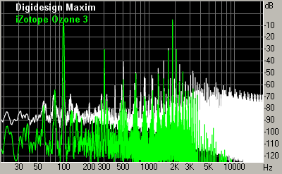
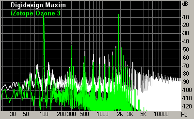
Smoothing of the gain envelopeUnfortunately breaks or sharp bends in gain envelopes are very common to many maximizers. They lead to similar breaks or bends in the output waveform. In terms of audio spectrum, it means that the spectrum of intermodulation distorion becomes wider, spanning more frequencies. This significantly increases the audibility of distortion. Indeed, when the gain envelope is smooth, the intermodulation distortion is grouping around peaks in the signal spectrum, where it has a high chance of being psychoacoustically masked by the signal. When breaks and sharp bends are present in the gain envelope, the spectrum of distortion is spreading in frequency and will more likely exceed the masking threshold. The distortion becomes audible as crackle. In Fig. 6, there are examples of 2 maximizers: with and without smoothing of gain envelopes.
Suggestions on the use of maximizersA maximizer should be the last link in the mastering chain. After maximizing, only bit depth reduction can take place (often it's combined with maximizing). All other processings, including sampling rate conversion, should be done before the maximizer, since they can change the peak levels of the waveform and lead to clipping or incomplete use of the medium dynamic range. During setup of maximizer parameters, the desired loudness of the recording should be a base point. Set the maximizer threshold according to the desired loudness increase, and after that start adjusting the aggressiveness. If intermodulation distortion is noticeable (e.g. rumbling at bass notes), decrease the aggressiveness (e.g. by increasing the release time). If the distortion is not noticeable, try a higher aggressiveness to reduce pumping effect and improve sharpness of transients. If the maximizer threshold is already set low, but the loudness is still not enough, other dynamics processors can be used. Try using a compressor. If even more loudness is needed - try a multiband compressor. If you are still not quite satisfied, check if your audio is already a pink noise. Limiters and maximizers can easily kill the microdynamics of your recording. The compression is usually done for esthetic reasons, but limiting - for technical reasons. And the technical stuff is better to be done by mastering specialists, who have a high-quality gear and reliable monitoring means. Comparison of maximizers quality
Now let's proceed to the testing of popular maximizers implemented as software plug-ins. Since there's no single adequate comparison criterion for maximizers, we are suggesting a few possible tests aimed at determining features and problems with maximizers. The following maximizers are currently participating:
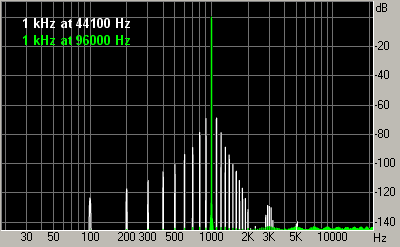
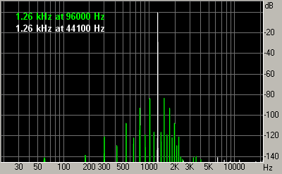
It should be mentioned that not all existing models are participating. We have chosen maximizers using 2 criteria: sound quality and popularity. We have deliberately excluded a popular Timeworks Mastering Compressor because it doesn't have a strict threshold and passes clipping. Also excluded is Steinberg Loudness Maximizer, because in most modes it deliberately introduces distortion into the signal. Criteria of comparisonWhat is the best way of comparing maximizers? Listening them in work! We'll suggest the conditions of experiment for better objectiveness of such a listening test. But first, let's review some existing maximizer comparisons from other sources and comment on their shortcomings. In article "Maximizers" by Alexey Zaitsev ("Music equipment", June 2001) the following approach is taken. The test sound consisting of 2 sinusoids is passed through maximizers (the test of intermodulation distortion). The spectrum analysis is performed on the result to estimate the level of non-linear distortion. All the tested maximizers are put into "equal" conditions by setting the same thresholds and release times. As we already know, equal thresholds and release times do not guarantee equal aggressiveness with different maximizers. That's why conclusions drawn from THD/IMD levels in that paper are not accurate. Another popular type of test brings the input and output waveforms to the sample amplitude and subtracts them. Such a test is often used to show how maximizers "spoil" the sound. Indeed, most of the resulting difference waveform is zero, but in the places where maximizer worked there are bursts of crackle or pieces of the original audio. It appears that such a test is only useful for finding the times when the maximizer worked. It doesn't allow judging about the sound quality of maximizer, similarly to how such a difference test doesn't allow saying much about the quality of e.g. noise reduction. The audibility of distortion cannot be evaluated separately from the main audio. Another popular test tries to detect the "best" sampling rate for a particular maximizer, at which the distortion is low. For example, 1 kHz sinusoid is taken and passed through maximizers at different sampling rates (44.1 kHz and 96 kHz). Then, by looking at distortion graphs (Fig. 9a), the conclusion is made that this maximizer sounds much cleaner at 96 kHz sampling rate. Such an illustration is present e.g. in Bob Katz' "Mastering Audio" book. However, in reality, the lower level of distortion at 96 kHz is just a coincidence for the particular test signal. The reason is that 96000 is divisible by 1000, but 44100 is not. So, the amplitude profile of this 1 kHz sinusoid has a complex shape when the sampling rate is 44.1 kHz, which pushes maximizer to following its shape and introducing additional harmonics. But if we take a sinusoid with a different frequency, e.g. 1260 Hz, then we can get quite opposite results for it (Fig. 9b).
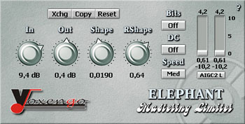
In reality, the level of distortions of maximizers may depend on the sampling rate. But this dependence is not always simple. Some devices are not accurately adapting their attack/release time to different sampling rates, so they end up having different aggressiveness. But even with the same aggressiveness, it happens that most dynamics processors have lower distortion (both at test tones and real audio signals) at higher sampling rates. For sinusoidal signals it can be easily explained by the fact that at higher sampling rates the amplitude peak profile of the digital sinusoid is closer to the constant, and the maximizer doesn't need to follow its bends and introduce modulation distortion. For real signals the explanation comes from the fact that intermodulation distortion is spread across a wider frequency range, and part of the distortion goes out of the audible range (while at lower sampling rates the distortion are getting aliased from ultrasound to the audible part of the spectrum). Some high-quality dynamics processors (e.g. Weiss) feature a so called double-sampling technology, i.e. oversampling of a digital signal before processing. The advantages of such a technology for maximizers are questionable, although it's present in some, e.g. Voxengo Elephant HQ (and, possibly, leads to slightly non-brickwall limiting). However for compressors some improvement of sound is reported. So, how can we improve the objectiveness of testing of maximizers? We suggest comparing the sound of maximizers only on real audio, using the same value of threshold and controlling the achieved aggressiveness to be the same. How the aggressiveness can be equated? Only by measuring the RMS power of the resulting signal. For example, the first maximizer outputs the signal with RMS = -9.25 dB, and the second one 0 having the same settings - RMS = -9.89 dB. Although the difference seems minor, it should be remembered that it's the average difference through the whole audio file. If we note that maximizers work only on a small fraction of the whole file (where the threshold has been exceeded), then it turns out that the loudness of really limited parts can be very different. So, the aggressiveness of 2 maximizers (at the given settings) is different, and we change the parameters of one of maximizers to make output RMS equal. Now, when both maximizers have the same aggressiveness, the listening evaluation can be performed. The first attention is usually drawn to audibility of intermodulation distortion, trembling and pumping, crackle and other induced artifacts. Since all the maximizers are now working in equal conditions and output the same loudness, the best one can be selected by listening. If it's nevertheless desirable to quote some objective results, tests of intermodulation distortion can be performed, where the overall level and spectral composition of distortions can be evaluated (of course, after settings maximizers to work with the same aggressiveness). In Fig. 6, there is a comparison of 2 maximizers at 2 different levels of aggressiveness. Within every graph, the aggressiveness of 2 maximizers is the same. From graphs of intermodulation distortion it is visible that highest peaks of distortion are almost matching in level, but spectrum spreading of distortion is very different. The audibility of distortion will be much higher for a maximizer with a wider distortion spectrum. In Alexey Zaitsev's article, it's suggested that the wide spectrum of intermodulation distortion in Timeworks Mastering Compressor reflects the work of special saturation algorithms, imitating tube distortion. Unfortunately, this is far from reality. The wide spectrum shown at the graph actually reflects clipping which is not prevented by this plug-in. It is not visible on the graph very well, but these distortions are not even harmonics of the test signal. Each of these "harmonics" consists of several closely spaced intermodulation tones. Moreover, the spectrum of tube distortion is considered valuable because of its high decay rate: only low-order first harmonics have considerable power. However, in case of maximizers, we usually deal with an infinitely decaying set of harmonics, whose spectrum is not quite like tube saturation, and whose sound is more like crackle (Fig. 8). Table of featuresIn this table, we are summarizing data about features of tested maximizers (or absence of certain problems). We have tried to evaluate most objective features that can be important for a high-quality sound. It can be expected that maximizers with similar features would also sound similarly. And even though a thorough listening is required for detailed analysis of sound quality, this table will tell many technical details to a skilled engineer about the possibilities of each tested maximizer. This table doesn't list features which are obvious from the documentation (e.g. presence of certain user controls), it evaluates specifically features of limiter algorithms. The order of the algorithms in the table does not necessarily reflect their quality rank, but of course it has a good relation to the quality of maximizers. Evaluated features:
DISCLAIMER: this table is not a rating of quality, it's a rating of algorithm features (that I personally consider important for limiters). Since I did an algorithm design for iZotope, Ozone has all these features implemented. Other manufacturers may promote other features, not present in this comparison.
Brief conclusionsThe best quality is demonstrated by maximizers with an auto release control technology. The Waves L2 maxmimizer has become a de-facto standard for high quality processing. It combines ARC technology with smoothing of gain envelope. One of shortcomings of L2 is that the option to detect inter-sample clipping has been pulled from it for some reason, although this function has been present in Waves L1+. Another problem is that its ARC mode doesn't have any adjustment of aggressiveness. The aggressiveness of L2 is relatively high (and indeed sounds loud), but with significant amounts of limiting come intermodulation distortions, which can only be avoided by disengaging the ARC algorithm and manually setting high release time.
Maximizer Voxengo Elephant HQ combines the auto release control mode with a possibility to adjust aggressiveness. This maximizers has gained some food user feedback, e.g. there are claims on a Voxengo forum that in many cases it sounds better than L2. This is completely possible, considering its adjustable aggressiveness in ARC mode. However this maximizer lacks some accurate engineering for achieving best results. For example, sometimes Elephant is not fully utilizing all the available dynamic range, and sometimes it passes a minor clipping. Also it doesn't have smoothing of gain envelopes, which leads to rather wide spectrum of distortion. In the newer version Elephant 2.0, a new EL-2 mode has been introduced that features smoothing of gain envelope and adjustable ARC aggressiveness. Still, a shortcoming of non-full utilization of the dynamic range remains (it limits below 0 dB FS level).
Intelligent Maximizer from iZotope Ozone 3 is a relatively new product. It combines ARC mode with adjustable aggressiveness, smoothing of gain envelopes and possibility of detection of "analog" peak levels. This maximizer has the best sound quality in many cases, it can be viewed as extension of Waves L2 towards adjustable aggressiveness and analog peaks detection.
ConclusionMaximizer is the mandatory device in any mastering studio, and it has a noticeable impact on the final sound of the recording. We have reviewed principles of operation of maximizers and main parameters defining their quality. Several simple tests suggested in this article allow easily evaluating the quality of other maximizers, not reviewed here. Additional reading
The author would like to thank Anatoly Veitsenfeld, Andrew Startsev, Andrey Subbotin, Vladimir Kuzmin and Ilya Prokhorov for an interesting discussion and valuable comments on the article.
|